First a disclaimer: You must fully understand the risks involved in carrying out procedures on this page. I am not responsible for anything that may happen to anyone or any property as a result of following instructions on this page. If you’re not comfortable with this then don’t read any more.
The information on this page is based on a number of posts by Paul Banks. All credits go to him and I advise you to visit his site first. The information is put here for posterity sake and for my own convenience so that I can easily repeat getting root access in future.
You need to be fairly comfortable with using a terminal and some Linux experience will greatly help in understanding the different steps of this process.
The steps to get root access to your Lidl (Silvercrest) Zigbee gateway and integrate it into Home Assistant are:
- Get the gateway’s root password.
- Setup device for use with Home Assistant.
- Using Home Assistant’s ZHA to integrate the device.
The process requires the following hardware:
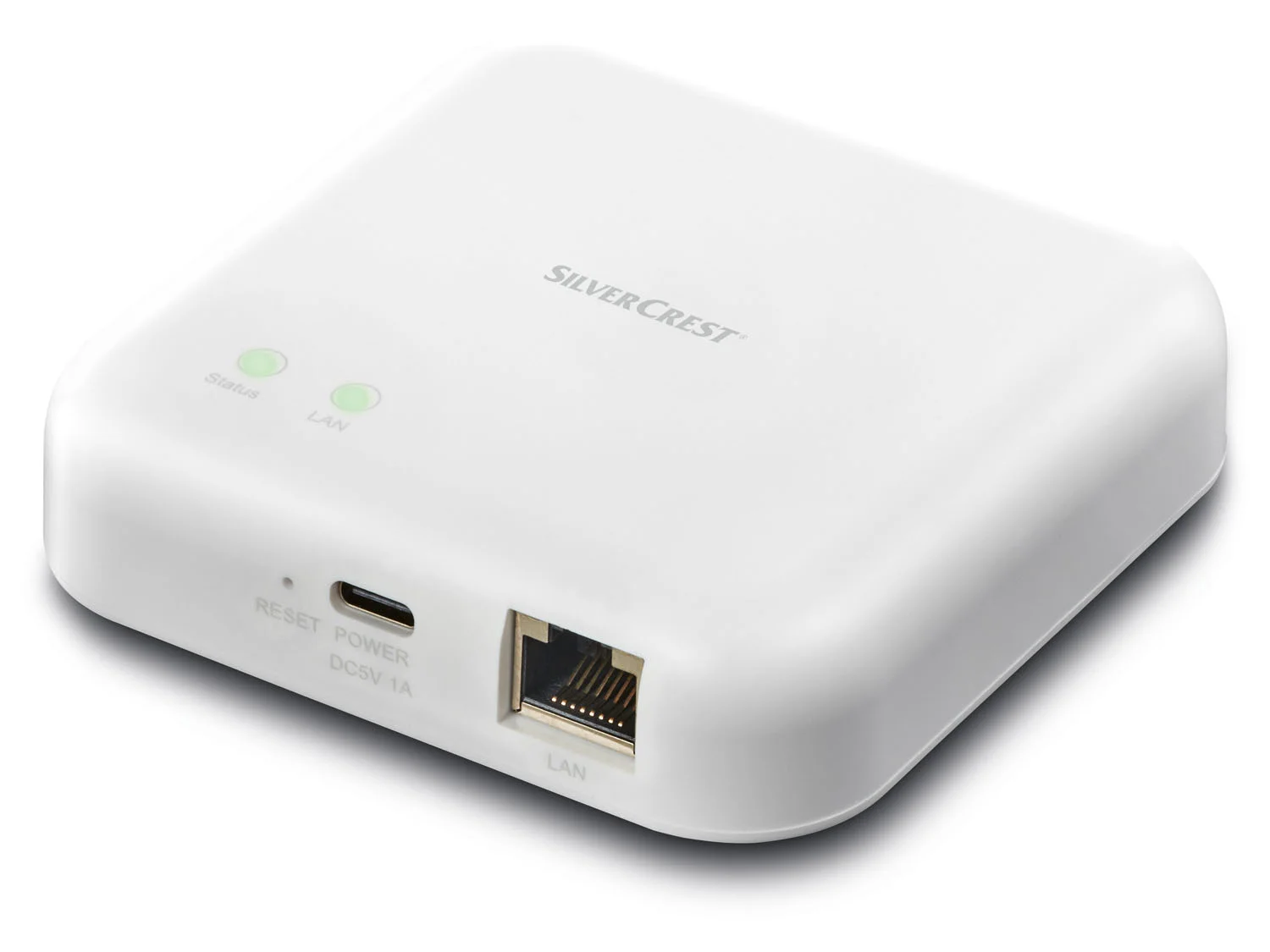
- Get the gateway itself (duh, I used this one).
- A USB to serial converter (I used this one).
- A six pin header for easy connecting Dupont cables to the gateway’s PCB.
- Three male to female Dupont cables to connect the USB to serial converter to the gateway’s PCB.
- A PC to communicate with the gateway via the USB to serial converter.
Required tools:
- Soldering iron (I used this one) with some solder wire and solder flux.
- Some repair kit for opening the snap fit case of the gateway (I used this one).
Get the gateway’s root password
The root password is set to the last 8 characters of AUSKEY which is some kind of identifier for the cloud services. The AUSKEY is stored, encrypted, in the SPI flash. (in the “tuya-label” partition.) The decryption key is also stored here so it is possible to recover the AUSKEY and thus also the root password for the device.
Getting the root password comprises three steps:
- Accessing the boot loader.
- Using it to read the raw encoded values from the flash.
- Decoding the values.
Accessing the boot loader
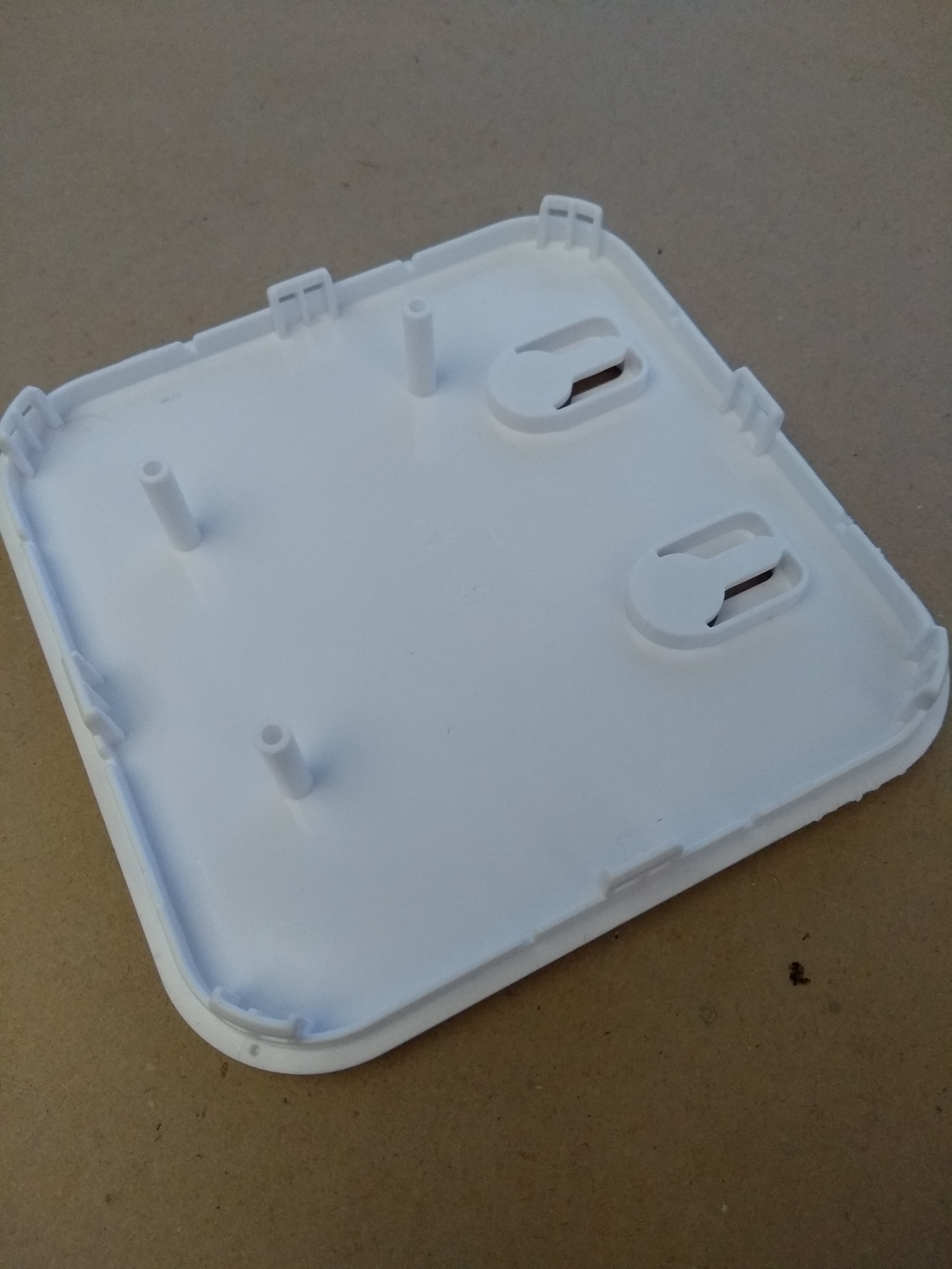
In order to access the boot loader you first need to disassemble the gateway. The home gateway uses a snap fit design to hold the case together. There are 8 plastic clips spread equally around the case and you need to work carefully around about half of them until you can separate the lid from the case.
Inside the gateway there is a single PCB featuring a main CPU, some RAM, an SPI flash chip, a separate ZigBee CPU, ethernet magnetics, LEDs, connectors and other supporting components.
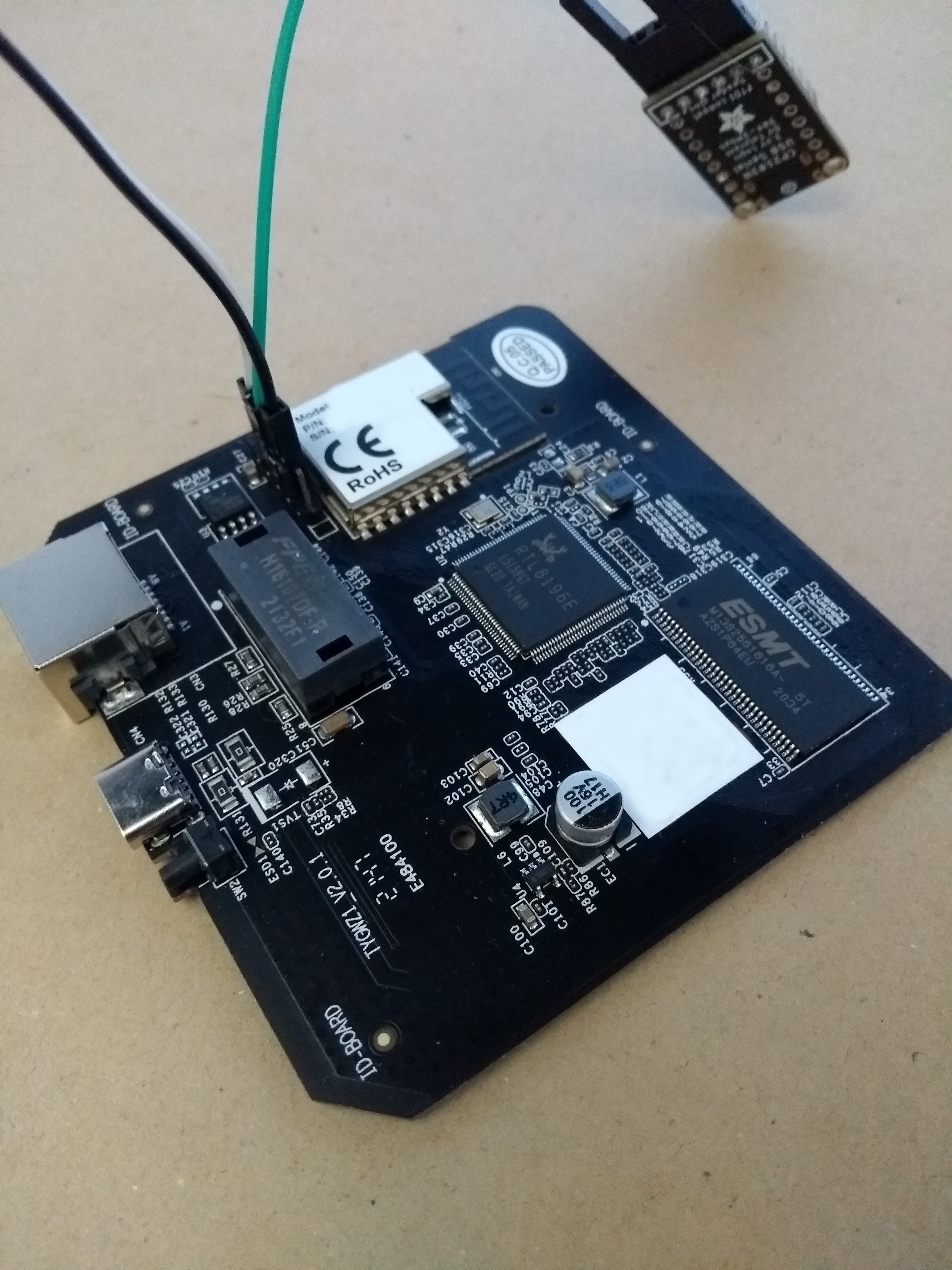
Main components are detailed here:
- U2 - A RealTek RTL8196E MIPS System-on-a-chip (SoC) CPU.
- U3 - A 16MB SPI Flash (GD25Q127)
- U5 - A 32MB SDRAM, EM6AA160.
- CN1 - A TuYa ZigBee module (TYZS4) which is based on a Silicon Labs ARM-M4 CPU with integrated RF stack. (EFR32MG1B232.)
- J1 - A Combined Serial port and ZigBee module ARM debug port. This is not usually populated - we added a header to ours.
The pinout of combined port is:
- Pin 1 = Vcc (3.3V) (bottom pin in picture)
- Pin 2 = Ground
- Pin 3 = U2 Serial TX
- Pin 4 = U2 Serial RX
- Pin 5 = ZigBee module ARM Debug SWDIO
- Pin 6 = ZigBee module ARM Debug SWCLK
Serial port parameters are:
- Electrical: TTL 3.3V
- Baud Rate: 38400 bps
- Other: 8N1 (8-bit, No Parity, 1 stop bit)
- No flow control (if you are unable to send keyboard command then make sure that flow control is turned off).
To connect a USB to serial converter you first need to solder a 6 pin header to the PCB (although a 4 pin header should suffice because for the purposes of getting root access you do not need pin 5 and 6).
I connected an Adafruit USB to Serial Converter to the gateway’s main board with a pin-out as below.
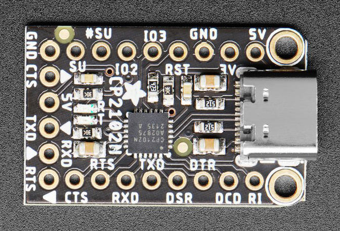
Notes for newbies: You must use a 3.3V TTL serial port to connect to this device. Connect only Ground (GND), TX and RX. Do not connect Vcc. Do not be tempted to connect the device directly to a PC serial port. Failure to observe these notes may damage your device.
Below is how I connected the combined port J1 to the USB serial converter, remember that TX connects to RX and vice versa.
| Combined port J1 | USB serial converter |
|---|---|
| Ground | Ground |
| U2 Serial TX | RXD |
| U2 Serial RX | TXD |
Double check to make sure that the converter is connected to the right pins on the PCB before plugging in the converter to your PC!
To successfully communicate you must first find out to which USB port the converter is connected to. I used the following command (Linux PCf):
sudo dmesg | grep converter
In my case the converter was connected to USB0. I then used the following command to start the communication process (this requires installing picocom):
sudo picocom -b 38400 /dev/ttyUSB0
If you properly connected the device to your PC (remember to connect TX to RX and vice versa), are able to read boot messages and can send keyboard commands then you can proceed to access the boot loader:
-
Power cycle the device whilst at the same time pressing the ESC key on the serial console. This should interrupt the boot process and end up at the RealTek boot loader prompt.
-
Press ENTER to get a fresh prompt.
It should look something like this:
---RealTek(RTL8196E)at 2020.04.28-13:58+0800 v3.4T-pre2 [16bit](400MHz)
P0phymode=01, embedded phy
check_image_header  return_addr:05010000 bank_offset:00000000
no sys signature at 00010000!

---Escape booting by user
P0phymode=01, embedded phy

---Ethernet init Okay!
<Real
<RealTek>
Read the raw encoded values from flash.
Reading the key-encryption-key (KEK)
The AUSKEY is itself encrypted by another key that we’ll call the KEK. To read the KEK, type the following commands into the boot loader. The first command reads the value from flash into RAM. This will ask for confirmation, answer with Y. The next one displays the contents:
FLR 80000000 401802 16
DW 80000000 4
Make a note of the single line of output. This is your KEK.
Read the encrypted AUSKEY
Use the following commands:
FLR 80000000 402002 32
DW 80000000 8
Make a note of the two lines of output. They are your encrypted AUSKEY.
Decode the values
The script below can be used to decode the AUSKEY and root password:
# Lidl Silvercrest SmartKey Root Decoder v0.2
#=============================================
# By Banksy
#
# PREREQ's:
#   Python 3
#   Install pycrypto Python library
#   You need to have opened your device and wired up a serial port to it.
#
# INSTRUCTIONS:
#
#  1) Attach TTY3v3 serial port to device.
#  2) Load terminal program, set params 38400, 8, N, 1 - NO FLOW CONTROL
#  3) Power on device and at same time, press ESC a few times.
#  4) You should end up at a <RealTek> prompt
#  5) Press ENTER
#  6) Type "FLR 80000000 401802 16" followed by enter to read the KEK from
#     flash into memory.
#  7) Type "dw 80000000 4" to display the KEK.
#  8) Type "FLR 80000000 402002 32" followed by enter to read the encoded
#     auskey from flash into RAM
#  9) Type "dw 80000000 8" to display the encrypted AUSKEY
# 10) Run this script
# 11) Paste the single line KEK output from step 7
# 12) Then paste the two lines of AUSKEY output from step 9
#
# Enjoy root.
#

import sys
if sys.version_info[0] < 3:
    raise RuntimeError("Python 3 is required to run this script!")
from binascii import unhexlify
import struct
from Crypto.Cipher import AES

def _aschar(b):
    return struct.unpack("b", bytes([b & 0xFF]))[0]

def _decode_kek(a):
    if len(a) != 16:
        raise ValueError("KEK incorrect length. Should be 16 was %d" % len(a))
    kek = []
    for b in a:
        c1 = _aschar(a[0] * b)
        c2 = _aschar((a[0] * b) // 0x5d)
        kek += [_aschar(c1 + c2 * -0x5d + ord('!'))]
    return bytes(kek)

def _get_bytes(a):
    a = a.replace(" ", "").replace("\t", "").split(":")
    return unhexlify(a[0] if len(a)==1 else a[1])

kek = _decode_kek(_get_bytes(input("Enter KEK hex string line>")))

encoded_key = b""
for n in range(2):
    a = input("Encoded aus-key as hex string line %d>" % (n+1))
    encoded_key += _get_bytes(a)

cipher = AES.new(kek, AES.MODE_ECB)
auskey = cipher.decrypt(encoded_key)

print("Auskey:", auskey.decode("ascii"))
print("Root password:", auskey[-8:].decode("ascii"))
Start the python script and, when prompted, paste the lines obtained above to reveal your auskey and root password.
You could also use a website to run the script if you are unable to run the code. Downside is that you run a security risk as the website then also could acquire the root password of your gateway.
Example decode run:
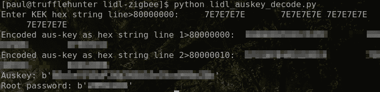
After booting up, you should be able to use the login command and put in root as user and the obtained password as password.
Setup device for use with Home Assistant
Before starting, ensure your device is on your local network. To obtain its IP address, issue an ifconfig command on the serial console.
To set up this device we need to:
- Make the Zigbee radio module available over TCP/IP.
- Backup the original Tuya boot script and instead set the TCP/IP gateway to boot on startup.
Make the Zigbee radio module available over TCP/IP
Download the program (source code and local copy of the program and copy it to the correct folder on the gateway (replace 1.1.1.1 with the IP address of the gateway on your local network):
cat serialgateway.bin | ssh -p2333 root@1.1.1.1 "cat >/tuya/serialgateway"
I had to modify the above command to gain SSH access:
cat serialgateway.bin | ssh -p2333 -oHostKeyAlgorithms=+ssh-dss root@1.1.1.1 "cat >/tuya/serialgateway"
Backup the original Tuya boot script and instead set the TCP/IP gateway to boot on startup
Modify the gateway’s boot script to disable the Tuya Applications and instead start the serial gateway.
On the device, using the ssh command as used above, execute the following:
if [ ! -f /tuya/tuya_start.original.sh ]; then cp /tuya/tuya_start.sh /tuya/tuya_start.original.sh; fi

cat >/tuya/tuya_start.sh <<EOF
#!/bin/sh
/tuya/serialgateway &
EOF
chmod 755 /tuya/serialgateway
This will backup the original tuya_start.sh script and replace it with a simpler one that simply starts the serialgateway program.
Using Home Assistant’s ZHA to integrate the device
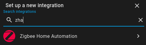
- Create a new integration of “Zigbee Home Automation”:
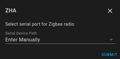
- Select enter manually for the port
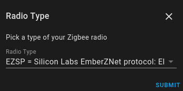
- Pick the EZSP radio type
- Enter the ip address of your device in this format socket://ip.address:8888
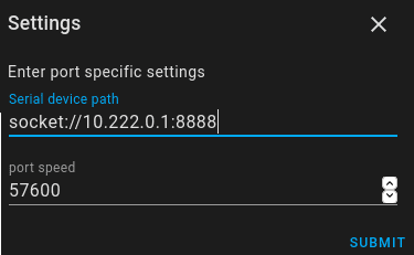
You can now start adding Zigbee devices to your gateway.
Last modified on 2024-05-24
Comments Disabled.